Buffer Overflow

Definition

A buffer overflow occurs when a program or process tries to store more data in a buffer than it was intended to hold. Since buffers are created to contain a finite amount of data, the extra information — which has to go somewhere — can overflow into adjacent buffers, corrupting or overwriting the valid data held in them. 
In buffer overflow attacks, the extra data may contain codes designed to trigger specific actions.

Reference

[1] http://searchsecurity.techtarget.com/definition/buffer-overflow

Address Space Layout Randomization (ASLR)

Definition

Address space layout randomization (ASLR) is a memory-protection process for operating systems to guards against buffer-overflow attacks by randomizing the location where system executables are loaded into memory.

Objective

The success of many cyberattacks, particularly zero-day exploits, relies on the hacker’s ability to know or guess the position of processes and functions in memory
ASLR is able to put address space targets in unpredictable locations. If an attacker attempts to exploit in an incorrect address space location, the target application will crash, stopping the attack and alerting the system.

Current Deployments

ASLR was created by the Pax Project as a Linux patch in 2001. 
  • It was integrated into the Windows operating system beginning with Vista in 2007. Prior to ASLR, the memory locations of files and applications were either known or easily determined. 
  • Adding ASLR to Vista increasing the number of possible address space locations to 256, meaning attackers only have a 1 in 256 chance of finding the correct location to execute code.
  • Apple began including ASLR in MAC OS X 10.5 Leopard, and Apple iOS and Google Andriod both using ASLR in 2011.

Reference

[1] http://searchsecurity.techtarget.com/definition/address-space-layout-randomization-ASLR

HoneyPots

Introduction

[1] Deception is a mechanism that attempts to distort or mislead an attacker into taking a course of action that is more suited to the goals of the defender.

A common deception defense is the use of network honeypots.

A honeypot is a commuter system that is designed to be a trap for unauthorized accesses.

Honeypots are deployed within a network to appear like normal, active systems to an outsider.

How to build honeypots

  • Mimicking
    • One of the deception technique is mimicking. A honeypot attempts to mimic a real system to fool the adversary into probing and/or attacking it. 
    • The amount of interaction the honeypots respond to queries with information that represents a possible system within the infrastructure but unlike a normal system, it maintains a very detailed logs of all interactions.  From these detailed logs, administrators can gain insight into an attacker’s goal and methods as well as put in place other measures to hopes of preventing an attack. 

Reference

[1] Probabilistic Performance Analysis of Moving Target and Deception Reconnaissance Defenses, by Michael Crouse, in MTD15

Cache in Virtualized Environments

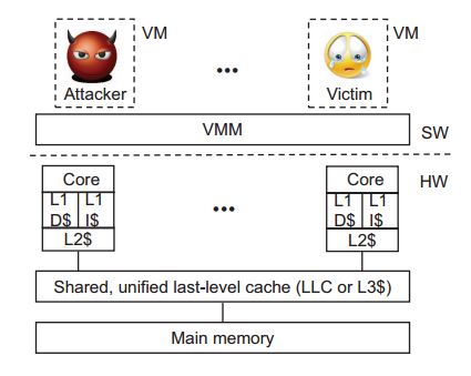
System Model for a Multi-core Processor

Cache Hierarchy

Reference [1]

Because of the long access time of main memory compared to fast processors, smaller but faster memory, called cache, are used to reduce the effective memory time as seen by a processor.

Modern processors feature a hierarchy of caches.

“Higher-level” caches, which are closer the processor core are smaller but faster than lower-level caches, which are closer to main memory.

L1 caches 

Each core typically has two private top level caches

  • 1) one for data
  • 2) one for instructions
A typical L1 cache size is 32KB with 4-cycle access time, as in Intel Core and Xeon families. 

LLC

The LLC is shared among all cores of a multicore chip and is a unified cache, i.e., it holds both data and instructions. [1]
LLC sizes measure in megabytes, and access latencies are of the order 40 cycles

L2 caches

Modern X86 processors typically also support core-private, unified L2 caches of intermediate size and latency. 

How it works

Any memory access first access the L1 cache, and on a miss, the request is sent down the hierarchy until it hits in a cache or accesses main memory. 
The L1 is typically indexed by virtual address. While all other caches are indexed by physical address. 

Cache Access

Reference [1]
To exploit spatial locality, caches are organized in fixed-size lines, which are the units of allocation and transfer down the cache hierarchy. 
A typical line size B is 64bytes.
The log2B lowest-order bits of the address, called the line offset, are used to locate a datum in the cache line. 

Set-associate 

Caches today are usually set-associate, i.e., organized as S sets of W lines each, called a W-way set-associative cache. As shown in the following figure.[1]
When the cache is accessed, the set index field of the address, log2S consecutive bits starting from bit log2B is used to locate a cache set. The remaining high-order bits are used as a tag for each cache line. 
After locating the cache set, the tag field of the address is matched against the tag of the W lines in the set to identify if one of the cache line is a cache hit. 

Cache Replacement

As memory is much larger than the cache, more than W memory lines may map to the same cache set, potentially resulting in cache contention. If an access misses in the cache, and all lines of the matching set are in use, one cache line must be evicted to free cache slot for the new cache line being fetched from the next level of cache or from main memory for the LLC. The cache’s replacement policy determines the line to evict. Typically replacement policies are approximations to least-recently-used (LRU). [1]
Traditional Cache

Per-Core Slice Cache

[1] Modern Intel processors, starting with the Sandy Bridge microarchitecture, use a more complex architecture for the LLC, to improve its performance.

The LLC is divided into pre-core slices, which are connected by a ring bus. Slices can be accessed concurrently and are effective separate caches, although the bus ensures that each core can access the full LLC (with higher latency for remote slices).

Sliced Cache

Ring bus architecture and sliced LLC

Reference

[1] Last-Level Cache Side-Channel Attacks are Practical, by Fangfei Liu et al, in Security&Privacy 2015

Virtual Address Space in Virtualized Environments

Page

Reference [1] 
  • A process executes in its private virtual address space, composed of pages, each representing a contiguous range of addresses.
  • The typical page size is 4KB
  • Each page is mapped to an arbitrary frame in physical memory

Address Mapping

Reference [1]
In virtualized environments there are two levels of address-space virtualization. 
1) the virtual addresses of a process -> guest’s notion of physical address, i.e., the VM’s emulated physical memory
2) guest physical addresses -> physical addresses of the processor

Page Translation

Reference [1]
Translations from virtual pages to physical frames are stored in page tables. 
Processor cache recently used page table entries in the translation look-aside-buffer (TLB).
The TLB is scarce processor resource with a small number of entries. 
Large pages used the TLB more efficiently, since fewer entries are needed to map a particular region of memory. As a result, the performance of application with large memory footprint, such as Oracle database or high-performance computing applications, can benefit from using large pages. 
For the same reason, VMMs, such as VMWare ESX and Xen HVM, also use large pages for mapping guest physical memory. 

Reference

[1] Last-Level Cache Side-Channel Attacks are Practical, by Fangfei Liu et al, in Security&Privacy 2015

Covert Channel Attack

Introduction

[1] Covert channels and side channels are two types of information leakage channels. A covert channel uses mechanisms that are not intended for communications, e.g., writing and checking if a file is locked to convey a “1” or “0”. 
In a covert channel, an insider process leaks information to an outsider process not normally allowed to access that information. The insider (sending) process could be a Trojan horse program previously inserted stealthily into the computer. An outsider (receiver) process need only to be an unpriviledged process. 

Reference

[1] Covert and Side Channels due to Processor Architecture, by Zhenghong Wang and Ruby B. Lee, in ACSAC 2006

Network Topology in the Cloud — ToR

Top of Rack

[1] demonstrates that most of the topology in Amazon Cloud is ToR mode.
  • All servers in a track are first connected to a separate Top of Rack (ToR) switch, and then the ToR switch is connected to aggregate swtiches. 
  • Such a topology has currently become a mainstream network topology in a data center.

Reference

[1] A Measurement Study on Co-residence Threat inside the Cloud, by Zhang Xu, Haining Wang and Zhenyu Wu, in UsenixSecurity2016

Virtual Private Cloud (VPC)

VPC Introduction

[1] VPC is a logically isolated networking environment that a separate private IP space and routing configuration. 

Characteristics

  • After creating a VPC, a customer can launch instances into VPC, instead of the large EC2 network pool. 
  • The customer can also divide a VPC into multiple subnets, where each subnet can have a preferred availability zone to place instances.
  • The private IP address of an instance in VPC is only known to its owner. It cannot be detected by other users. Thus, it can significantly reduces the threat of co-residence. 

Reference

[1] A Measurement Study on Co-residence Threat inside the Cloud, by Zhang Xu, Haining Wang and Zhenyu Wu, in UsenixSecurity2016